前路经寰枢关节交叉螺钉固定技术——应用基础研究篇
2020-07-07 文章来源:南方医科大学南方医院脊柱骨科 季伟 我要说
原标题:
前路经寰枢关节交叉螺钉固定治疗寰枢关节不稳的可行性及钉道分析:一项基于尸体标本的新技术研究
摘要
目的:在前路经寰枢关节螺钉(ATS)固定不适用或失败的特殊情况下,经枢椎椎体对侧隆突的前路经关节交叉螺钉(ATCS)固定可作为一种可选的内固定方式并增强其稳定性,并实现寰枢椎关节融合。本研究旨在介绍一种新的治疗寰枢关节不稳定的ATCS固定技术及其应用解剖研究,并与ATS固定方法进行比较分析。
方法:使用数字卡尺和量角器对30对干燥的人体C1和C2椎骨标本进行了直接测量。使用直径4.0mm的中空拉力螺钉对11例新鲜颈椎标本进行ATS和ATCS固定,并分别测量两种置钉方式的进钉角度以及螺钉在C1和C2椎骨内的长度。最后对全部标本进行解剖以观察ATS和ATCS固定技术分别对其周围重要结构损伤情况。
结果:寰枢椎有足够的骨空间实施ATCS固定技术,其外展和尾倾置钉角度分别为36.2°和28.7°。ACTS固定技术在C2椎体的钉道长度(25.6mm)明显大于ATS技术(11.4mm),而在二者C1椎体上的钉道长度相似(ATCS 14.8mm,ATS 14.9mm)。ATCS固定后并未观察到椎动脉沟、椎管或者寰枕关节的损伤。
结论:前路经寰枢关节交叉螺钉固定是寰枢椎固定的一种可行的选择。这一技术实现了螺钉钉道的显著延长,并可增强寰枢椎固定的稳定性。
关键词:寰椎,枢椎,交叉螺钉,前路,经关节螺钉
背景
前路经关节螺钉(ATS)固定治疗寰枢关节不稳定最早于1971年由Barbour[1]提出。1998年,Lu等人[2]对ATS固定进行了解剖学研究。直到2003年,Reindl等人使用Smith-Robinson标准方法报道了[3]技术,才有关于这一技术的进一步研究。两年后,该研究小组进行了生物力学研究,证实了该技术在寰枢椎稳定中的有效性[4]。至此以后,逐渐有一些使用微创或经皮手术的技术改良被报道[5-10]。
然而,在一些特殊的临床情况下,这些常见的固定技术可能不适用、出现失败,或者需要辅助固定。C2侧块关节前皮质边缘骨折在ATS固定后较少发生[7,11]。但ATS固定失败引起骨性解剖结构破坏可导致ATS再次固定的安全性及有效性大大降低。作为对于这些特定情况的补救,经过C2对侧隆突的前路经关节交叉螺钉(ATCS)固定可以行寰枢关节稳定治疗。
在本研究中,我们提出了一种新的寰枢椎内固定技术。此外,通过对骨的形态测定研究和使用人类尸体脊柱标本评估螺钉轨迹,并与ATS固定方法进行比较,评估其在解剖学上的可行性。据我们所知,这种技术尚未有相关文献报道。作为我们正在进行的研究的一部分,后期将进行有关生物力学稳定性评估。
材料和方法
干骨的测量
解剖学部提供了30对干燥的寰椎、枢椎标本,这些标本的种族、性别和年龄不详。ATCS固定相关详细的形态学参数测量,包括左、右C1关节面最大宽度和前后径,C1侧块的左右侧及内侧高度,左、右C1下关节面与横断平面的夹角(图1a、b)。同时测量椎体中线处C2前后椎体高度,C2椎体正中矢状面上、下的前后径及下终板水平处C2椎体宽度(图1c、d)。
使用精确到0.1毫米的数字卡尺测量的(Mitutoyo Corp;Tokyo,Japan)来进行所有的线性测量,角度测量使用精确到1°的量角器进行记录。
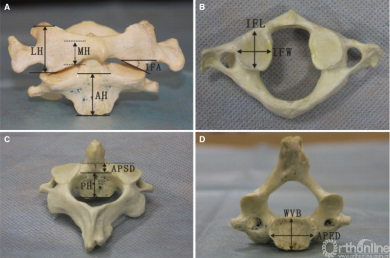
图1 C1和C2椎体线段及角度测量:a、LH侧块的侧边高度,MH侧块的内侧高度,IFA下关节面相对横截面的角度,AH枢椎椎体前缘高度;b、IFW下关节面宽度,IFL下关节面长度;c、PH枢椎椎体前缘高度,APED前后终板距离;d、WVB椎体宽度,APSD椎体前后宽度
新鲜尸体标本的ATCS固定
采集-20℃冷冻的11具新鲜人体尸体颈椎节段(枕骨-C4;6M/5F;平均年龄46岁;年龄段36–71岁)。采用侧位和前-后位的X线片排除明显的肿瘤、创伤、先天性疾病、早期手术或小关节病变。于手术当天解冻标本,每个标本置钉完成后进行局部解剖观察。
进钉点及螺钉轨迹
两种前路经寰枢关节螺钉固定技术:ATS和ATCS,如图2。ATS固定术进钉点位于C2椎体中下部前外侧的凹槽内,即C2椎体水平中点线上,寰枢椎侧块关节面内侧三分之一处[4,12]。ATCS固定术进钉点位于距离C2下终板上方5mm,距中线往外3-5mm处,使螺钉头部和C2-C3椎间盘之间有一个合适的距离,以防止相邻节段骨化的发生。为了减少对标本的损伤,在每个标本的左侧或右侧随机行一次ATCS和ATS固定。
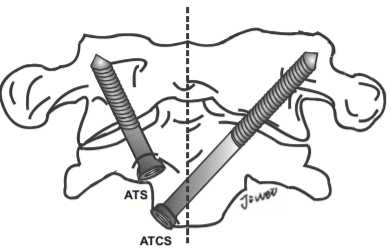
图2前路关节螺钉(ATS)固定和前路经关节交叉螺钉(ATCS)固定示意图
ATS和ATCS固定的轨迹可通过正、侧位X线片上的解剖标志来确定。在正位X线片中,螺钉轨迹朝向C1上关节突上外侧角,与侧块外侧缘间隙为2-3mm(图3,左)。然后测量α角,即ATS与ATSC螺钉相对于矢状面所形成的理想外展角。在侧位X线片中,ATS和ATCS固定方向均朝向C1上关节突后上角,并与上关节突后缘的间隙为2.3mm(图3,右)。此外,还测量了角β,即ATS与ATSC螺钉相对于冠状面所形成的理想倾斜角。将螺钉置入新鲜尸体标本后,在正、侧位X线片上分别测量ATS和ATCS的实际角α、β,以及ATCS和ATS的实际进钉点与C2椎体中线的横向距离。
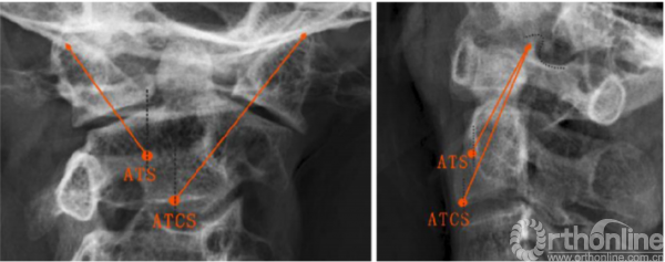
图3正位和侧位x线片上ATS和ATCS的螺钉轨迹,(左)所有螺钉对准C1上关节突上外侧角;(右)所有螺钉对准C1上关节突上角(点附近);ATCS,前路经关节交叉螺钉;ATS,前路关节交叉螺钉
螺钉长度及C1、C2椎体内钉道长度
所有螺钉的直径均为4.0mm,这与以往临床和生物力学研究中所用的直径相同[4,10,13]。用深度计测量无明显皮质骨突破时螺钉的最大允许长度。取出螺钉,将标本行枕部和C2分离,并去除前方软组织,观察两种固定方法损伤椎动脉(VA)沟、椎管或寰枕关节的情况。此外,测量从C1侧块关节下关节面的钉道口至C1侧块骨折内钉道末端的距离,以及C2进钉点至C2上关节面的钉道口的距离。分别对ATS和ATCS进行以上相应测量。
统计分析
结果以均数±标准差表示。采用配对t检验比较C1椎体左右解剖参数及ATS和ATCS之间的尺寸与角度差异。所用统计软件为SPSS13.0版(Chicago,IL),将P<0.05被认为有统计学意义。
结果
干骨的测量
所有的线性和角度测量以及左右的统计差异如表1和表2所示。同一参数的左、右两侧的测量结果均无统计学差异。C1下关节面与水平面所成角度为29.6°±5.0°。侧块的外侧和内侧高度分别为18.2±2.5mm和10.0±2.3mm。下关节面宽度和长度分别为分别为16.0±1.7mm和17.3±1.7mm。C2椎体高度前缘(19.5±1.6mm)大于后缘(16.2±1.5mm)。C2下终板宽度为19.7±2.4mm,C2下终板水平椎体前后径(17.1±1.5mm)大于C2椎体上缘前后宽度(10.9±1.7mm)(表2)。
表1. C1椎体解剖参数
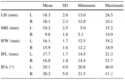
SD标准差,LH侧块外侧高度,MH侧块内侧高度,IFW下关节面宽度,IFL下关节面长度,IFA下关节面相对横截面角度,L左,R右。
表2. C2椎体解剖参数
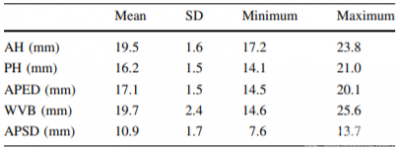
SD标准差,AH椎体前缘高度,PH椎体后缘高度,APED终板前后缘距离,WVB椎体宽度,APSD椎体上缘前后宽度。
新鲜尸体标本的ATCS固定
所有标本均成功完成ATCS和ATS固定,未见C1椎动脉沟、椎管及寰枕关节损伤。ATCS和ATS实际进钉点与中线的侧方距离分别为5.0±1.1mm和13.0±1.5mm。ATCS固定理想的外展角和倾斜角分别为38.3±4.1°和30.7±2.9°,而ATS分别为29.6±2.7°和34.3±2.5°。理想螺钉角度与实际螺钉角度无统计学差异(P<0.05)。螺钉置入后(图4),x线测量ATCS相对矢状面实际外展角大于ATS。然而,ATCS相对于冠状面的实际倾斜角小于ATS(表3)。
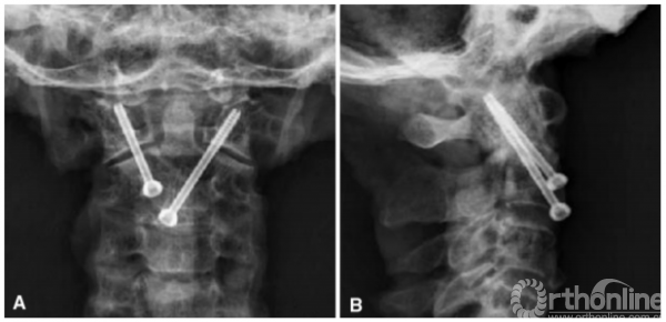
图4前路经关节交叉螺钉固定前后位x线片(a)和侧位片(b)视图
表3 11具新鲜尸体颈椎的螺钉长度和角度

测量值以平均值±标准差表示,ATCS前路经关节交叉螺钉,ATS前路关节螺钉,*表示与ATCS的差异(P<0.05)
C1/C2的螺钉长度及钉道长度汇总见表3。总体上ATCS的螺钉长度(40.4±2.2mm)明显大于ATS(26.4±3.1mm)(P<0.001)。ATCS固定在C1骨质内的钉道长度为14.8±1.6mm,与ATS相似(14.9±1.5mm)。但ATCS在C2骨质内的钉道长度为25.6±1.6mm,明显大于ATS的11.4±1.7mm(P<0.001)。
讨论
前路经寰枢关节螺钉固定技术可采用开放或经皮微创手术完成,但两种手术方式其螺钉的进钉点有所不同。在开放手术中,其进钉点位于C2椎体前外侧的骨性凹槽内,即C2椎体水平中线与寰枢侧块关节面内侧1/3相交处。螺钉以冠状面上外展20°和矢状面上倾斜30°置入C2椎体,并穿过寰枢侧块关节的前缘部分[4]。经皮微创ATS固定的螺钉轨迹穿过C1-C2侧块关节中部,进钉点位于C2椎体的前下缘,离中线5mm到10mm处,冠状面上外展20°至30°,矢状面上倾斜20°至28°[9]。以上文献报道的ATS螺钉角度与本研究测量到的ATS的实际角度相近。
然而,在一些特殊的情况下,这些常用的固定方法可能不适用,或者需要再辅助固定。C2侧块关节面前缘骨折在ATS固定后较少发生[7,11]。但当ATS固定失败后,C2椎体同侧几乎没有留下安全有效的再次置钉位置,这时ATCS作为补救技术,可以再完成寰枢关节前路稳定固定。
Cacciola等人[14]观察到79%的椎动脉位于C2上关节突下表面的椎动脉沟内,57%的椎动脉沟位于C1后弓外侧。在这种情况下,由于存在医源性VA损伤的潜在风险,后路经关节螺钉固定是不可行的[15,16]。在这种情况下,ATS固定也很困难。对于椎动脉解剖正常的患者,以C2上关节面为中心的ATS轨迹为理想的螺钉通路。
相反,当患者椎动脉高跨时(图5a),为避免椎动脉损伤,ATS螺钉轨迹应位于C2上关节面前部,矢状面上的倾斜角减小,而螺钉在C2椎体骨质内的长度减少也增加了螺钉从侧块关节面切割失败的风险。然而,对椎动脉高跨的患者实行ATCS固定(图5b),其螺钉经过具有较高骨密度的C2隆突,椎体骨质内的螺钉长度也显著增加。因此,可以预估ATCS固定比ATS固定更稳定。
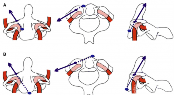
图5 ATCS(a)和ATCS (b)螺钉轨迹示意图(蓝色箭头)显示VA异常C2的ATS(a)和ATCS(b)螺钉轨迹,VA为椎动脉
作为一种治疗寰枢椎不稳的内固定技术,ATCS固定技术在以下几个方面优于ATS固定。首先,ATCS以C2椎体前下缘隆突为进钉点,便于识别。其次,ATCS的螺钉长度(40.4mm)明显长于ATS(26.4mm),螺钉周围有较多的骨质,具备更好的力学稳定性。再次,行ATCS固定可从一侧切开暴露完成置钉固定,避免了双侧切开暴露及软组织剥离,减少了损伤,也更不易损伤椎动脉。然而,ATCS固定方法作为一种新的内固定技术,还需要进行生物力学评价。
干骨的解剖研究表明,寰枢椎有足够的骨性空间行ATCS固定。C1下关节面宽度和长度分别为16mm和17mm,均大于螺钉直径(4mm)。C2下终板左右径和前后径分别为20mm和17mm,足够放置2枚螺钉。C2椎体高度足够容纳单侧置入两枚螺钉。理论上,寰椎和枢椎的尺寸满足双侧ATCS固定的要求。
双侧ATCS固定技术在C2关节皮质前缘双侧螺钉切出、骨缺损及C2椎动脉高跨的患者中具有优势。此外,双侧ATCS固定使用较长螺钉能够加强稳定性,但仍需进一步的生物力学研究评估。
使用该新技术时,术前应常规采用薄层CT扫描来评估来定位椎动脉的走形情况。因此,术前规划中将CT扫描图像结合钉道的设计是很有必要的。其次,术中推荐采用双平面的透视。此外,本研究的样本量较小,可能会导致测量参数的偏差。
结论
前路经寰枢椎关节交叉螺钉固定是可行的,可作为寰枢椎不稳内固定治疗的一种选择。在临床应用前,需进一步行生物力学研究验证,但使用该项新技术其较长的螺钉长度可有利于防止螺钉拔出。
原文速览
Feasibility and trajectory study of anterior transarticular crossing screw placement for atlantoaxial joint instability: a cadaveric study and description of a novel technique
Abstract
Purpose: In unique clinical situations where C1–C2 anterior transarticular screw (ATS) fixation is not available or has failed, an anterior transarticular crossing screw (ATCS) with transcorporal pathway of the screws inside the contralateral promontory of C2 may enhance the stabilization and achieve atlantoaxial arthrodesis. The present study was to describe a novel technique of ATCS fixation for atlantoaxial joint instability and its applied anatomy, and compared it with ATS fixation method.
Methods: Direct measurements using digital calipers and a goniometer were conducted on 30 pairs of dried human C1 and C2 vertebrae. The ATS and ATCS with screws (U 4.0 mm) were performed on 11 fresh cervical spine specimens. The screw lengths in the C1 and C2, and screw entry angles of the ATS and ATCS were measured, respectively. Cadaver specimens were dissected to observe the incidence of violation to the important structures surrounding the ATS and ATCS fixation technique.
Results: There was enough osseous space for ATCS placement. The lateral and incline angle of the ATCS was 36.2 and 28.7, respectively. Screw purchase in C2 of the ATCS (25.6 mm) was greater than that of the ATS(11.4 mm). The ATCS C1 purchase (14.8 mm) was similar to the ATS C1 purchase (14.9 mm). No violation to the vertebral artery groove, the spinal canal or the atlanto-occipital joint was observed after the ATCS placement.
Conclusion: Anterior transarticular crossing screw is a feasible and viable option for atlantoaxial fixation in selected cases. This technique achieved remarkable longer screw purchase and could enhance the atlantoaxial stability
Keywords: Atlas ; Axial ; Crossing screw ; Anterior approach ;Transarticular screw
Introduction
Anterior transarticular screw (ATS) fixation for atlantoaxial joint instability was first described by Barbour [1] in 1971. In 1998, Lu et al. [2] conducted an anatomic study for ATS fixation. There had been no further studies on the topic until Reindl et al. [3] reported on the technique using a standard Smith-Robinson approach in 2003. Two years later, the same team performed a biomechanical study and confirmed the effectiveness of this technique in atlantoaxial stabilization [4]. Since then, some modification in surgical techniques using minimally invasive or percutaneous surgical procedures have been reported [5–10].
There are, however, unique clinical situations in which these common fixation techniques may be impossible, have already failed, or require supplemental fixation. Fracture of the anterior cortical rim of the C2 articular bone occurs rarely after ATS [7, 11]. Failed attempts at placement of ATS disrupted osseous anatomy are associated with fewer landmarks for reposition safe and effective ATS. For these unique salvage or rescue situations, the availability of anterior transarticular crossing screw (ATCS) with transcorporal pathway of the screws insdie the contralateral promontory of C2 may stabilize the atlantoaxial joint.
In this study, the authors propose a new technique of ATCS fixation for atlantoaxial fixation. Furthermore, the anatomic feasibility is assessed through a morphometric study on dry bones and an evaluation of screw trajectories using human cadaver spine specimens, and compared with ATS fixation method. To our knowledge, this technique has not been published in the English literature. As part of our ongoing research, we plan to evaluate the biomechanical implications of this new method.
Materials and methods
Measurements on the dry bones
Thirty pairs of dried atlas and axis specimens were provided by the Department of Anatomy. The race, sex, and age of the specimens were unknown. The detailed morphometric parameters related to ATCS were measured, including the left and right maximum widths and anteroposterior diameters of C1 inferior facet articular surface, the left and right lateral and medial heights of C1 lateral mass, the left and right angles of C1 inferior facet relative to the transverse plane (Fig. 1a, b). We also measured the C2 anterior and posterior vertebral body heights in the midline of vertebral body, the superior and inferior anteroposterior diameters of C2 vertebral body in the midsagittal plane, the C2 vertebral width at level of the inferior endplate (Fig. 1c, d).
All linear measurements were obtained using a digital caliper accurate to 0.1 mm (Mitutoyo Corp; Tokyo, Japan) and the angular measurements were recorded with a goniometer accurate to 1.
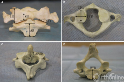
Fig. 1 Linear and angular measurements of C1 and C2 vertebrae. a LH lateral height of lateral mass, MH medial height of lateral mass, IFA inferior facet angle relative to transverse plane, AH anterior height of vertebral body. b IFW inferior facet width, IFL inferior facet length. c PH posterior height of vertebral body, APED anteroposterior endplate diameter. d WVB width of vertebral body, APSD anteroposterior superior vertebral diameter
ATCS placement on fresh cadaveric specimens
The craniovertebral junction segments (occiput-C4) from 11 fresh human cadaveric cervical spines were harvested (6 M/5F; mean age, 46 years; age range, 36–71 years) and frozen at -20 C. Lateral and anteroposterior X-rays were taken to exclude obvious neoplastic, traumatic, congenital conditions, earlier surgery, or facet arthropathy. The spines were thawed on the day of surgery. The surgical dissection was performed on each specimen after the screw placement.
Screw entry points and trajectories
Two kinds of anterior transarticular screw fixations for atlantoaxial joint were determined (Fig. 2): ATS and ATCS. For ATS fixation, the entry point was set at just below the sulcus on the anterior body of the C2, located at the midpoint of the C2 body in the medial third of the C1–C2 facet joint [4, 12]. For ATCS fixation, the entry point was set at a point 5 mm cranial to the anterior edge of the C2 end plate and 3–5 mm lateral from the midline to the contralateral side, to provide an allowable distance between the screw head and the C2–C3 intervertebral disc to prevent adjacent level ossification development. In order to reduce the damage to the specimen, ATCS and ATS were random.

Fig. 2 Artist’s illustrations showing the anterior transarticular screw (ATS) fixation and the anterior transarticular crossing screw (ATCS) fixation
The ATS and ATCS trajectories were determined using the landmarks visible on anteroposterior and lateral x-rays. On the anteroposterior view, screw trajectories were aimed at the superolateral corner of C1 superior articular process, leaving 2–3 mm clearance from lateral margin of the lateral mass (Fig. 3, left). Then, the angle α, the ideal lateral angle of ATS and ATCS placement relative to the sagittal plane were measured. On the lateral view, the trajectories of ATS and ATCS were aimed at a point on the line between the superoposterior corner of C1 superior articular process and the superior end of the anterior arch, with 2–3 mm clearance from posterior margin of the superior articular process (Fig. 3, right). Moreover, the angle b, the ideal incline angle of the two screws placement relative to coronal plane were measured. After the screws were inserted into fresh cadaveric specimens, the actual angle a and b of ATS and ATCS were also measured on anteroposterior and lateral X-ray images, respectively, as well as the actual entry points of ATCS and ATS lateral from the midline of the C2 vertebrae.

Fig. 3 Trajectories of ATS and ATCS are shown on anteroposterior (left) and lateral radiographs (right). (left) All screws are aimed at the superolateral corner of C1 superior articular process; (right) All screws are aimed at the superoposterior corner of C1 superior articular process (around dot). ATCS anterior transarticular crossing screw, ATS anterior transarticular screw
Screw length and lengths of C1/C2 purchase
The diameter of the both screws was 4.0 mm, the same diameter used in previous clinical and biomechanical studies [4, 10, 13]. The maximum allowable screw lengths in the absence of any cortical breach were measured with a depth gauge. The screws were removed, the specimens were disarticulated from the occiput and C2, and the anterior soft tissues were removed. Incidence of violation to the vertebral artery (VA) groove, the spinal canal, or the atlanto-occipital joint was observed for the two fixation techniques. In addition, the length of C1 purchase was measured from the cortical margin at the inferior articular surface of C1 to the end point. The length of the C2 purchase was measured from the screw entrance to the cortical margin at the C2 superior articular surface. These measurements were done for ATS and ATCS, respectively.
Statistical analyses
The results were presented as the mean ± standard deviation. Paired t-test was used to compare the left and right anatomic parameters of C1 vertebral body, as well as dimensions and angles between ATS and ATCS. The statistical software used was SPSS version 13.0 (Chicago, IL). Statistically significant differences were set at a p<0.05.
Results
Measurements on the dry bones
All linear and angular measurements and statistical differences between the left and right are shown in Tables 1 and 2. There were no statistical differences in any measurements between sides. The angle of the C1 inferior facets relative to the transverse plane was 29.6 ± 5.0.The lateral and medial height of later mass was 18.2 ± 2.5 mm and 10.0 ± 2.3 mm, respectively. The inferior facet width and inferior facet length was 16.0 ± 1.7 mm and 17.3 ± 1.7 mm, respectively.
Table 1 Anatomic parameters of C1 vertebral body
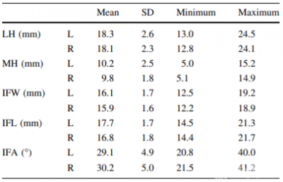
SD standard deviation, LH lateral height of lateral mass, MH medial height of lateral mass, IFW inferior facet width, IFL inferior facet length, IFA inferior facet angle relative to transverse plane, L left, R right.
Table 2 Anatomic parameters of C2 vertebral body
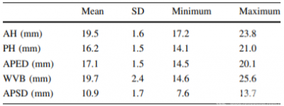
SD standard deviation, AH anterior height of vertebral body, PH posterior height of vertebral body, APED anteroposterior endplate diameter, WVB width of vertebral body, APSD anteroposterior superior vertebral diameter.
ATCS placement on fresh cadaveric specimen
The ATCS and ATS were inserted successfully into all specimens without any violation to the VA groove of C1and C2, or the spinal canal. Neither was there any violation to the atlanto-occipital joint. The actual entry points of ATCS and ATS lateral from the midline was 5.0 ± 1.1 mm and 13.0 ± 1.5 mm, respectively. The ideal lateral and incline angles were 38.3 ± 4.1 and 30.7 ± 2.9 for the ATCS, and 29.6 ± 2.7 and 34.3 ± 2.5 for the ATS, respectively. There was no statistical difference between the ideal and the actual screw angulations (p<0.05). After the screws were inserted (Fig. 4), the actual lateral angle of the ATCS relative to sagittal plane was greater than that of the ATS measured on anteroposterior X-rays. On the contrary, the actual incline angle of the ATCS relative to coronal plane was smaller than that of the ATS (Table 3).
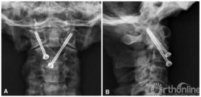
Fig. 4 The anterior transarticular crossing screws fixation is shown on anteroposterior (a) and lateral radiographs (b), respectively
Table 3 Screw length and angulations measured on 11 fresh human cadaveric cervical spines

Values are mean ± standard deviation,ATCS anterior transarticular crossing screw, ATS anterior transarticular screw,* Indicates difference from the ATCS (p<0.05)
The screw lengths and lengths of C1/C2 purchase were summarized in Table 3. Overall, the ATCS length (40.4 ± 2.2 mm) was significantly longer than the ATS length (26.4 ± 3.1 mm) (p<0.001). The ATCS length of C1 purchase was 14.8 ± 1.6 mm, and similar to the ATS length (14.9 ± 1.5 mm). The ATCS length of C2 purchase was 25.6 ± 1.6 mm, and longer than the ATS length (11.4 ± 1.7 mm) (p<0.001).
Discussion
Two types of ATS placements are used for open surgery and percutaneous minimal invasion surgery with different screw entrances. For the open surgery, the entry point was set at just below the sulcus of the anterior C2 body, and located at the midpoint of C2 body and the medial third of C1–C2 facet joint. The screw was inserted into the C2 body 20° medially on the anteroposterior view and 30° the cephalic on the lateral view, crossing the atlantoaxial joint just anterior to the midpoint [4]. The percutaneous ATS trajectory passed through the middle of the C1–C2 facet joint, and the recommended entrance was at the inferior border of the C2 body and off the midline 5 mm to 10 mm, with 20° to 30° medial in the anteroposterior view and 20° to 28° cephalic in the lateral view [9]. Those screw angulations were similar to the actual angles of the ATS measured in this study.
However, there are unique clinical scenarios in which these common fixation methods may impossible and require supplemental fixation. Fracture of the anterior cortical rim of the C2 articular bone occurs rarely after ATS [7, 11]. When failed attempts at placement of ATS leave few landmarks for a safe and effective ATS reposition, the ATCS, as a salvage or rescue technique, may enhance the stabilization to the atlantoaxial joint.
Cacciola et al. [14] observed that the artery occupied, on average, 79 % of the VA groove on the inferior surface of C2 superior articular facet and approximately 57 % of the VA groove over the lateral part of C1 posterior arch. In this situation, the posterior transarticular screw fixation is impossible due to a potential risk of iatrogenic VA injury [15, 16]. Placement of ATS would be also difficult under such circumstances. For the patients with normal VA, the ATS trajectory at the center of the C2 superior articular surface is considered as an ideal screw passageway. In contrast, when patients have high-riding VA (Fig. 5a), the ATS trajectory should be located anteriorly at the C2 superior articular surface with a smaller posterior entry angle in order to avoid the VA injury, but reduce the screw purchase to the C2 and increase the risk of screw cutout. However, ATCS placement for patients with high-riding VA (Fig. 5b) with the transcorporal pathway of the screws inside the vertebral body of C2, increases screw purchase inside the C2 promontory with higher bone mineral density [17], and adds stability to the construct. In addition, the length of ATCS was remarkably longer. Therefore, it is anticipated that the ATCS fixation would be more stable than the ATS fixation.
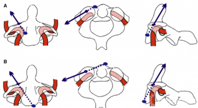
Fig. 5 Schematic drawings showing ATS (a) and ATCS (b) screw trajectories (blue arrow) in C2 with anomalous VA. ATCS anterior transarticular crossing screw, ATS anterior transarticular screw. VA indicates vertebral artery
As a salvage or rescue surgical technique for the treatment of atlantoaxial instability, the ATCS fixation technique was superior to the ATS fixation method as following aspects. Firstly, the ATCS passes through the promontory of anterior cortex C2 as a landmark, allows 4–6 mm off ipsilaterally as the entry point of ATCS, which can be identified easily. Secondly, the length of ATCS (40.4 mm) was remarkably longer than that of ATS (26.4 mm), which should be favor to resistance to screw pull-out. Thirdly, unilateral incision and exposure of the C2 avoids dissection of the contralateral soft tissue and VA injure. However, the ATCS fixation method as a novel screw fixation technique should be evaluated biomechanically in future.
The present anatomical study on the dry bones indicated that there was enough osseous space for the ATCS placement. The C1 inferior facet width and inferior facet length was 16 and 17 mm, respectively, which were greater than the diameter of the screw (4 mm). The width and anteroposterior diameter of the C2 body at the inferior endplate was 20 and 17 mm, respectively, which were enough for 2 screws. The C2 body height was of an adequate space for two screws inserted unilaterally. Theoretically, dimensions of the atlas and axis meet the requirement for bilateral ATCS placement,
The technique of the bilateral ATCS fixation may be advantageous in patients with two side screw cutout and insufficient bone at the anterior cortical rim of the C2 articular for an appropriate fixation, and in patients with two side high-riding arteries in the C2 segment. Moreover, bilateral ATCS using longer screws should enhance the fixation, which will be evaluated in our ongoing biomechanical study.
This technique should not be attempted without pre-operative CT evaluation to locate the vertebral arterial groove and to assess the feasibility in a given patient. Therefore, preoperative planning is essential, including combination of CT images with the proposed screw trajectory. Biplane fluoroscopy is recommended intraoperatively. Furthermore, the sample size of the present study is small and may contribute to variation of the measured parameters.
Conclusion
Anterior atlantoaxial transarticular crossing screws appears feasible and may eventually be an alternative option for atlantoaxial fixation techniques. A biomechanical study of the anterior atlantoaxial transarticular crossing screws is necessary before clinical application. The remarkable longer screws used in this technique should be favor to resistance to screw pull-out.
参考文献
1. Barbour JR (1971) Screw fixation in fractures of the odontoid process. S Aust Clin 5:20
2. Lu J, Ebraheim NA, Yang H et al (1998) Anatomic considerationsof anterior transarticular screw fixation for atlantoaxial instability. Spine 23:1229–1235
3. Reindl R, Sen M, Aebi M (2003) Anterior instrumentation for traumatic C1-C2 instability. Spine 28:E329–E333
4. Sen MK, Steffen T, Beckman L et al (2005) Atlantoaxial fusionusing anterior transarticular screw fixation of C1-C2: technical innovation and biomechanical study. Eur Spine J 14:512–518
5. Li WL, Chi YL, Xu HZ et al (2010) Percutaneous anterior transarticular screw fixation for atlantoaxial instability: a case series. J Bone Joint Surg Br 92:545–549
6. Padua MRA, Yeom JS, Lee SY et al (2013) Fluoroscopically guided anterior atlantoaxial transarticular screws: a feasibility and trajectory study using CT-based simulation software. Spine J13:1455–1463
7. Koller H, Kammermeier V, Ulbricht D et al (2006) Anterior retropharyngeal fixation C1-2 for stabilization of atlantoaxial instabilities: study of feasibility, technical description and preliminary results. Eur Spine J 15:1326–1338
8. Cavalcanti DD, Agrawal A, Garcia-Gonzalez U et al (2010)Anterolateral C1-C2 transarticular fixation for atlantoaxial arthrodesis: landmarks, working area, and angles of approach.Neurosurgery 67:38–42
9. Wang J, Zhou Y, Zhang Z et al (2012) Minimally invasive anterior transarticular screw fixation and microendoscopic bone graft for atlantoaxial instability. Eur Spine J 21:1568–1574
10. Kansal R, Sharma A, Kukreja S (2011) An anterior high cervical retropharyngeal approach for C1-C2 intrafacetal fusion and transarticular screw insertion. J Clin Neurosci 18:1705–1708
11. Polli FM, Miscusi M, Forcato S et al (2015) Atlantoaxial anterior transarticular screw fixation: a case series and reappraisal of the technique. Spine J 15:185–193
12. Xu H, Chi YL, Wang XY et al (2012) Comparison of the anatomic risk for vertebral artery injury associated with percutaneous atlantoaxial anterior and posterior transarticular screws. Spine J12:656–662
13. Lapsiwala SB, Anderson PA, Oza A et al (2006) Biomechanical comparison of four C1 to C2 rigid fixative techniques: anterior transarticular, posterior transarticular, C1 to C2 pedicle, and C1to C2 intralaminar screws. Neurosurgery 58:516–521
14. Cacciola F, Phalke U, Goel A (2004) Vertebral artery in relationship to C1-C2 vertebrae: an anatomical study. Neurol India52:178–184
15. Peng CW, Chou BT, Bendo JA, Spivak JM (2009) Vertebral artery injury in cervical spine surgery: anatomical considerations,management, and preventive measures. Spine J 9:70–76
16. Finn MA, Apfelbaum RI (2010) Atlantoaxial transarticular screw fixation: update on technique and outcomes in 269 patients.Neurosurgery 66:184–192
17. Kandziora F, Schulze-Stahl N, Khodadadyan-Klostermann C,Schroder R, Mittlmeier T (2001) Screw placement in transoral atlantoaxial plate systems: an anatomical study. J Neurosurg95:80–87
主译简介

季伟
季伟,医学博士,南方医科大学南方医院脊柱骨科副主任医师。
主要从事上颈椎临床及基础研究,擅长并专注颅颈交界区疾患、脊柱畸形、脊柱肿瘤及感染的诊治。目前主持国家自然科学基金1项、南方医院杰出青年培育计划1项及院长基金1项。
近年来在国内外主流期刊《Spine J》《Spine》《European Spine J》《中华骨科杂志》及《中国脊柱脊髓杂志》等共发表文章25篇,其中20篇论著为SCI收录(第一或通讯作者身份),并获10项国家发明/实用新型专利。
参于编辑《脊柱内固定解剖学》,参于翻译《脊柱影像学》。目前为《中国临床解剖学杂志》青年编委,《Pain Research and Management》杂志客座编辑,《CLINICS》杂志审稿人。
相关阅读:





 京公网安备11010502051256号